Thursday, March 19, 2015

Getting Wired.

A while back, I referred to a conversation that had something to do with wiring and how much I enjoy it. I think part of why this assertion might have come across as completely bogus less than credible is that some of the people who are joining us here have actually seen what the wiring in the car looked like before I gracelessly yoinked it out of everything forward of the dashboard.
 
When I put the car together the first time, one of my goals was to minimize any irreversible modifications. For one thing, that meant that I'd avoid drilling new holes. For another, it meant that I'd use as much of the original car as I could. Mostly. The problem with this approach is that the fusebox didn't match the wiring diagram. Nor did some of the wires. So for a long time, I drove around with the original nasty looking - yet completely functional - fusebox, connected to similarly nasty looking original wiring:


Some of those wires aren't original, and the inline fuse holder certainly came along later. But this ugly thing met my Zero Permanent Impact priority.
 
I'd like to note that this car has never once blown a fuse since I've owned it. You can pooh-pooh me and my Reduce Reuse Recycle approach to motoring all you want, but my shit works. Aside from the fact that the car has been laid up for more than six months, I mean. In normal use on a street car, I mean. In a completely mundane non extreme environment where it's not expected to meet any standard for excellence, I mean. Where there aren't any safety inspectors for old cars, I mean. Dead reliable.
 
Once all the wires were pulled to the cabin side of the firewall, everything made perfect sense:

 
That snaggle of wires had to stay like that for a few weeks, as there were some fundamental changes to the wiring layout pending, and I didn't want to (further) upset anything that was in the car until I had a better idea of which wires would be removed, which would be rerouted, which would be replaced, where new ones would be added, etc etc.
 
While I was panicking mapping this all out in my mind, I took decisive action. Like as though I might change my mind on the whole deal or something. Anyway, I drilled a hole in the cowl for the required battery disconnect switch:
 

I have this vision that I'll be sitting at a red light and some smartypants pedestrian will reach over and shut the car off before the light turns green. I'd totally do that to someone if I had the chance.

The battery disconnect has to fully shut off all the electricity to the car, so if you have an alternator, you'll want to ensure that you get a switch that prevents the alternator from frying itself if you throw the switch while the engine is running. If the power that the alternator is producing suddenly has nowhere to go, it can self destruct. So I'm told.

Adding this switch changes the routing of the Big Power Wire that used to lead from the alternator to the ammeter and then on to the starter. We could have routed the alternator through the ammeter and then to the cutoff switch (thus retaining a functional ammeter), but decided to bypass the ammeter altogether. Fewer terminals and connections for this critical wire means fewer chances of voltage drops or faulty connections. The car has an amp light and a voltmeter. Those should be enough to monitor the relative health of the charging system as a whole. We tossed the 10 gauge stuff and replaced it with 8 gauge also, as Automotive Electrical Smart People say that 10 gauge is only good for up to 30 amps. We have more than 30 amps.

One thing about electric stuff in old cars: the electricity generally goes from the source (the battery, or the generator or alternator) side of things, through the switch, and on to the load (lights, fan, wipers, etc). This is alright (sort of), but if you make the electrical pathways shorter and use larger gauge wiring, you reduce the possibility of a voltage drop (actually, a few possibilities for voltage drops) between the source and the load. It might seem like a lot of effort for a minor improvement, but it's really worthwhile - the electrical load on the switch(es) is greatly reduced (this is a good thing) and the electricity faces a lot less resistance on its way to the load side of things. If you're dealing with lights, know that a 10% drop in voltage to the bulbs themselves reduces light output by about a third. You want full voltage at the bulbs.

Also, if you're going to do something silly and run a pair of 80/100 watt H4 bulbs that come in a box that says "not for use on public roads," you may well overwhelm the original wiring in the car. Melting the insulation off the wires is only cool if later that evening you can talk about how it didn't burn your car to the ground.

We don't want this. Image credit: http://datsunpanamericana.blogspot.com/2010/10/actalizaciones.html
The ol' Volvo is now fitted with a second fusebox, a junction block from a 240 (that's the black rectangle on the left), a reverse relay from a 122 (the round canister next to the black rectangle) and five relays taken from various wrecking yard 240s:


The use of old relays instead of fancy new ones is certainly questionable. Part of the problem is that when I recently ordered some "Hella 40 amp relays" online, the things that arrived weren't Hella branded at all and weren't manufactured in any of the countries I'd associate with Hella. So until I find some suitable, high quality relays to use, I'm going with the "Bosch from back in the old days when their quality control was top notch" for now.

Because I like using old things, I came very close to installing a second fusebox taken from another PV series Volvo. But that seemed a little overboard with the Vintage Factor and lacking in the High Reliability Factor. Form follows function. Or something.

Once I'm not completely behind on getting the car on the road, I'll return to the relays and fit the car with whatever Daniel Stern recommends. He's probably the smartest automotive lighting specialist in North America. Check him out here:

http://www.danielsternlighting.com/

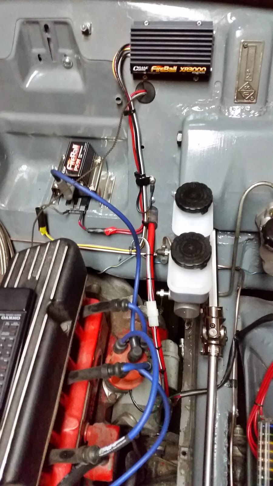
The ignition stuff comes next. Though I'm generally happy with points and condsensors (and I sure do like that they're easily replaced alongside the road on dark and stormy nights), we wanted something more macho for this application. This led to a few conversations and more researching, and that led to a Crane XR3000 (a lot like the more common Crane XR700 but more expensive) and a PS91 'Fireball' coil. If it's called 'Fireball' it probably kicks serious rump. It looks more like something the Terminator uses than it does an ignition coil.

Even with the heater removed from the firewall, there's not a lot of room for things like high zoot coils and ignition boxes. We thought about putting the coil on the pedal box, but chose to keep it away from the hydraulics, just so that ' various things that might need servicing' aren't all cramped together. So the coil went where the battery used to be:

I'm not completely happy with this layout from an aesthetic perspective, but it meets the 'functional and easily serviced' criteria. And there's room leftover in the battery box for other things. Not sure what other things, exactly...

One way to encourage promote enhance reliability is to add redundancy. The 5 relays shown above are one example - we're only going to use 3 of them, and the other two are standing by so that if one relay fails, we just move two wires over to one of the unused ones.

Along this line of thinking, and because we want as many of the controls and monitors accessible by both the driver and the codriver, most of the controls for the electrics have been moved to a panel located in the middle of the car.


The foot switch for the hi/lo beam selector has been replaced by a DPST toggle on the left, next to that an SPST toggle for the fog light. Next to that is a switch that activates the reverse light (these cars didn't have reverse lights, so ours has a 55w Cibie Tango foglight on the back of the car). The 'normal' reverse light switch on the transmission is also in place but we may find a reason to light up everything behind the car at a time that we don't actually want to be driving backward. Tailgaters beware.

All LCP cars have to have Hazard Lights, so we added a switch for those. If you look online, you'll find fancy kits to retrofit 4 way flashers onto an old car that didn't come with them. The kits have plenty of wires with diodes and a relay and they cost about $60. Instead of that, we bought a flasher relay for $4 at the local auto parts store and wired it between 12v+, through the switch, then on to the wires that lead to the car's turn signals. Simple. Works nicely. If you do this, use a DPST switch so that you can run separate wires to the left and right lights, otherwise you'll create a feedback loop and all 4 lights will flash when you activate the turn signals.

Next to that is will be a fan override. The electric cooling fan has its own temp sensor and an adjustable switch, but we want to be able to run the fan if that system should fail. So there'll be a switch for that.

Finally there's a switch for a siren. We're required to have loud horns (and we do) but we're adding a siren so that we can make a whole lot of noise if needed (and we may put an alarm in the car, strange as that sounds). We're hoping that during the race we might pass someone, and to do that, you have to announce your presence. The codriver gets his own horn button also, though that's not yet in place.

The indicator lights on top of the dash are just so we know when different things are working (or not). The larger lamps on the left are oil pressure and amp warning lights (444s didn't come with those), and the smaller ones are just monitors for the fog light, reverse light, and fan. We want to know when the fan turns on and off, and we don't want to drive around with fog or reverse lights on when we don't need them.
 
The fusebox is tidier than before also, and to keep things easy to service, is now labeled both with load items and wire colors:
 
I don't have any of the little short 25amp fuses around anymore, but after adding a second fusebox, really don't need more than these 4. The 4 contacts on the upper right are connected, so though it doesn't look like the white fuse is getting any power, it actually is. Red = B+ direct, Green = switched 12v.

The very good news is this: we hooked up the battery and nothing bad happened. Instead, every single thing that has to do with the new wiring stuff works exactly as intended. Super cool.

And that's actually where the car is at this point. The only remaining tasks before we can test drive the car are to get the fan wired, bleed the brakes, and connect up the clutch hydraulic lines. Then there's a whole long list of things to do after it runs and drives. We'll get to that when the time comes.

Cheers --

Tuesday, March 10, 2015

Carburetors.

You might have noticed that things are slowing down a bit and that posts are less... focused... than when we began a few weeks ago. Things are still moving forward, but given that I only have one or two days a week to put into the car (and I'm working alone right now), the project isn't exactly moving blindingly ahead.
 
Also, sometimes things don't go very well and I end up burning up a whole day on a task that I really thought would take a couple hours. Today was such a day. One of the days last week was, too.
 
Anyway, here's a refresher of what things under the hood used to look like. Of note is one pair of SUHS6 carburetors, which are [if I may say so] one of the most elegantly designed and highly functional carburetors in the history of engines. Presto:
 
 
Those carbs are now sitting on the shelf in the garage, where they'll wait for some other project, or maybe I'll hear from someone interested in buying a professionally rebushed set with proper needles for a B20 and K&N elements tucked into the original filter housings.
 
SUs like that are just dandy for engines that produce up to something around 140hp, and for engines that produce more than something around 140hp, larger carbs are warranted. And as terrific as SUs are, they're British, and British things are considered kind of stodgy (which, of course, is absurd). Italian things, on the other hand, are considered really sexy and also functional, though perhaps a little finicky. My wife is Italian, so she's probably an expert but I haven't decided to ask her about the finicky part.
 
My friend with the Fiat summed it up nicely, "It's Italian. If I can start it, it will WIN!"
 
Enter the legendary Weber 45 DCOE.
 
A guy I used to work with told me that DCOE stands for "Double Carburetors On End." That's not quite right, but it's close enough for us Americans. Doppio Corpo Orizzontale something something. I'd run a pair of 42 DCOEs on this car when I first put it together, which I later sold, but managed to come up with a pair of 45s more recently which were, sadly, not being used. Neglect is a real problem for DCOEs. Horrible waste.
 
The first thing to do was to test fit the forward carburetor. The intake manifolds that are being used are much longer than the old Warnerford piece that I'd used before, so I anticipated cutting a hole in the inner fender.
 
With the inner fender removed:
 

Yep. Gonna cut.

If we'd stuck with the old manifold, cutting wouldn't be necessary. But that intake has a couple fairly sharp bends that the fuel mix would have to navigate on its way into the engine, which doesn't help fuel atomization and can lead to an increase in turbulence (which is a good thing in some places but not in the intake charge. At least not to this degree. Er.. it works pretty well, it's just not ideal, and we want ideal).

The other thing that's preferable about a longer intake manifold is that there's a whole science behind optimizing the fuel mixture beyond just 'reducing turbulence.' Smart people have measured how well a Volvo engine will run with different length intake manifolds as the variable, with carbs and engines as constants. In short, there's an ideal distance between the carburetor and the intake valve, and those short manifolds come up... uhm... short.

There are a few long manifolds on the market that are functionally excellent - TWM and MISAB come to mind - but the Holy Grail (far as I'm concerned, anyway) are the VCS [Volvo Competition Service] intake manifolds. Back before Volvo came up with the R-Sport line, they offered factory made race car parts through their VCS Catalog, which hardly anyone knew about and dealers did little to promote (thus, the rarity of all the bits they offered). No other intake manifold is as appropriate as these. Functionally excellent, and genuine Volvo.

I'd owned a pair of such manifolds [NOS, no less] some years ago (actually, two pairs) but had sold them when finances were dire. As this project was coming together, I contacted the fellow who'd bought one of the sets and he very graciously agreed to sell me another NOS pair he had on hand.

They're only NOS until someone installs or alters them, after which their market value decreases. They become "used." I happily committed this travesty and stuck 'em on the car.

Once the manifolds are fitted with the carbs, the carbs have to connect to the gas pedal. Most of the racers I've seen use a really sweet dual cable assembly that does an excellent job, but I wanted the old school rods and levers setup.

One real benefit to the cable setup is that the effective throttle input doesn't change if or when the engine rocks. Even so, we're going with rods and levers. Sexy billet aluminum levers fitted to industrial strength stainless steel rod. It looks like this:


One nice thing is that the setup is really adjustable, as all the little arms cinch down on the shaft that runs back to front. As long as you line everything up super carefully, it works very well.

Rod and levers and a support and a lockring:


Another view, from a different angle. The excess rod has been cut from the forward end (see the black line? Right there):


... and from the front. The inner fender is now in place, with a big honker of a hole in it. The splash shield isn't in place (actually, it hasn't even been made yet). Also please ignore the crap that's laying across the top of the carbs:


These last two pics illustrate the difference in length between the VCS manifolds (top photo) and the Warnerford (lower pic). Sorry the scale is so completely off:


The benefit of the Warnerford is that you don't have to cut away your inner fender. No big deal on a PV, as these are replaceable pieces, but if you have a 122 or an 1800, you might think twice about it. I'm told that the Warnerford is the only option for a right hand drive Volvo, so if you're in Australia, that's probably the one you'll want.
 
The other benefit to the shorter manifolds is that the carbs aren't hanging way off in space away from the engine. We'll devise some kind of support. Probably.
 
And that's about it. We're nearly caught up with the car's current state, which is kind of cool. I'd hoped to take a test drive later this week but it's not looking promising with recent setbacks. We'll see how tomorrow goes.
 
Cheers -

Thursday, March 5, 2015

Keeping One's Cool.

I was talking to my friend Alden (really, he's more family than friend) a couple weeks ago about this project and said something like "Pretty soon, it'll be time to rewire the forward half of the car and the dash. I'm looking forward to that."

Pause.

"Uh.... yeah." The kind of "Uh... yeah" that actually means 'that doesn't sound like any fun at all and I might be thinking you're a fool not only for thinking that but also for admitting that out loud.'

Consider, though: wiring a car is one of the cleanest things you can do (besides wash the thing). No oil, coolant, fuel, hydraulic fluid, metal shavings or any of that kind of stuff. There's a Zen quality to it, which to some degree transfers over to the process of fabbing up brakelines.

I had a similar conversation about those (brakelines, I mean) not too long ago (but I can't remember who I was talking with). I like them. I like what they do, and I like the process of bending and flaring them and putting them on the car. I also like the idea of removing the original steel lines from this car and replacing them with something that isn't 58 year old steel that spent a few years in wet mud. Probably overdue.

I was enjoying this process recently, as everything was going really well until I was flaring the very last piece and broke the little flaring fitting thing inside the brakeline itself. Normally, this wouldn't be an issue and I'd just go get another flaring fitting thing and start with a new piece of hydraulic line, but this was the last one I had. They break pretty easily. Instead of going out and looking for a replacement, it became clear that the brakes would wait and that moving on to other things made much more sense.

*#$*##!:


That little black piece should have a teeny little shaft sticking out of the middle. In this photo, that teeny little shaft is inside the nicely bubble flared brakeline. See the clog in the end? Yeah.

If you don't have this little thing, you can make a single flare, and lots of people do. That's not good enough for your brakes.

As the engine compartment became more populated with 'stuff cars need,' the outside of the car got another change. One of the things that makes Old Volvo Engines really great (and run forever) is that they have a lot of bearing surface. Bearing surfaces generate heat, though, and the oil gets hot, and the hotter the oil is, the less effective it is at 1) keeping expensive and critical things inside the engine the right kind of slippery; and 2) moving heat away from the bearing surfaces it's supposed to protect. The oil still tries to move the heat away from the bearings, but if you're running the engine really hard (like you might while racing), the bearings generate enough heat that the oil never gets to cool down. This kills engines. We can't have that.

Enter the oil cooler. These are really just radiators, but instead of being full of coolant or water, they're full of oil. The oil gets hot in the engine then travels to the oil cooler where it's cooled, then it goes back to the engine and keeps things lubed while dissipating heat like it's supposed to.

Wanting to compare competitors spread my business around, I called Summit Racing and talked to a guy on their tech line. After a few minutes, we had a shopping list and I ordered up an oil cooler, some super sweet high pressure hose that's sheathed in braided gold pressed latinum, an adaptor to mount on the engine side of things and a remote oil filter bracket so I could put the oil filter on the firewall where it'd be easier to access, and a handful of AN fittings to connect it all together.

You really need high zoot stuff for this, because oil is at really high pressures, and the whole system has to withstand those while also being filled with hot oil while being connected to something relatively prone (the chassis) as well as something that wiggles all the time (the engine). Don't go adapting a coolant radiator to your car's lubricating system. I haven't tried it, but my guess is that the result will suck.

When the box arrived, I found that the adaptor wasn't the one I'd asked for, and the AN fittings were the 90 degree angled variety. For one, you don't really want to use a 90 degree fitting in this application if you don't have to; and for another, the fittings screw into the remote filter bracket right next to one another... so after you get one screwed into place, it's completely in the way of allowing the other one to screw into place. I'd have thought the tech guy would have known that he was filling a box with incompatible parts.

I decided to nix the remote filter thing, and put a different adapter (a 'sandwich,' it's called) on the engine. This one allows the original filter to fit about like it used to while also providing for the AN fittings and uber sexy hoses that will lead to the cooler itself.

To ensure that the cooler gets enough airflow, it goes in the front of the car where all the headwind is. Putting it in front of the radiator would be simplest, but it would also block the radiator (only a little, but a little is too much).

First, I measured the size of the cooler itself and then drew an outline on the front of the car where the new hole would go:


The corners aren't simply square, because (as usual) I wanted to make the first hole smaller than necessary. Easier to make a hole larger than to make it smaller:


And that whole 'hard to remove Sharpie from the paint later on' thing isn't an issue this time. I'll be removing these marks along with the paint and metal beneath them. Cue sinister cackling.

I'd been given a Sawzall, so I figured I'd put it to use on this task. Not as messy nor scary as an angle grinder, but every bit as exhilarating. Trouble is, though, that it chips the paint. The angle grinder doesn't do that, because it's busy generating a wicked ton of heat, and that softens the paint so that big chips don't go flying. Into your face.

After the hole was cut, the cooler went into place. A piece of sheet aluminum riveted into place hides the paint chips.


... that silver coil thing in the grille opening is one end of the braided oil line that isn't yet connected. The little blue and red things are the fittings that connect the hose to the cooler.

AN fittings are pretty fancy things. And they use wrenches that are specific to AN fittings, which means you can either gall them with a bench vise and an adjustable wrench, or you can buy the fancy AN wrench. I bought the wrench and found it no more nor less likely to gall the fittings. Save the $14.

Fun fact: the adjustable wrench was invented in Sweden. So was the zipper.

As you probably know, sharp bends for something like an oil line are not recommended. Fittings on the hoses and connected to the cooler:


Quick view to confirm that the grille surround doesn't tangle with the aluminum:


Fitted:


As usual, I've read a whole bunch of articles about doing this kind of thing, and I've got a fair amount of experience working with these old Volvos (curse, or blessing? you decide). But I've also had a whole lot of insight from people whose experience is well beyond my own. As the process continues to unfold, I've been in communication with race organizers (have to ensure that the car is being assembled within the regulations - so far, so good), with Jim Perry (he and I will be switching roles between driving and navigating and breaking things and fixing things) and with Phil Singher. A few years ago, Phil was tasked with putting together a Volvo 122 for La Carrera. The short story is that after Phil gave it some serious thought and a lot of attention, the car won its class.

You can read more about that Volvo - the Apple Farmer 122 - here:

http://applefarmerracing.com/car.html

Parts used in this installment came from Jeg's: www.jegs.com and Summit Racing: www.summitracing.com . If you'd like a bargain on some oil cooler and remote filter pieces, let me know. I still have the stuff I can't make use of.

'til then, then. Cheers -

Tuesday, March 3, 2015

Steering and Surgery.

Onward.

I don't do construction, but there's a process you kind of have to follow if you're going to do something huge, like build a house. You can't start with the windows, and the roof can't go up before the walls are in place, and before that, you have to slather cement all over the ground. There's a whole rhetoric born of this notion that's applied to Pretty Much Everything Anyone Ever Wants To Do that requires more than two steps. Something about starting with a good foundation.

I don't know whether my foundation is sound (I sure hope so), but I do know that each thing that happens has to happen in a specific order. Some stuff can happen before or after some other stuff, but a lot of it can't be switched around. For example: it's a bad idea to wire the car before you paint it.

For this project, the stuff that fits between the body of the car and the ground (thing that hold the wheels on, I mean) takes first priority. Axle and crossmember placement dictate where brakelines get routed, for example, and wiring has to happen after that, and nothing can be allowed to interfere with the steering parts, and there's not a lot of wiggle room for where those go.

Compounding all of this [for my little brain] is that although it's not hard to envision what has to happen, it all has to happen in open space. It's not always as simple as "insert tab A into slot B." It's a 3D model with X, Y and Z axises  axisies axes all arguing over who gets to be the most important. My role has been to sweet talk the brakes (or the steering) into realizing that they really are every bit as important as the steering (or the brakes). No more, no less.

At least that's how I view it. Mostly because I can't decide whether I'd rather have complete brake failure or complete steering failure at race speeds on a 7% downgrade on a mountain road. Either would suck.

Now that it was all naked under the hood, it was time to address the steering and the pedal placement. I went about these at the same time, as the pedal placement dictates where the steering shaft goes, and the placement of the steering box (which can't be moved around) as well as the placement of the steering wheel (ditto that) dictate where the steering shaft goes.

Yeah, I did say that twice. All three of those things have equal influence over the steering shaft. Add the next weird detail - that the pedals have to be where the pedals belong, and you end up with the wacky brain hurting 3D thing I just mentioned. I thought about this every night while drifting off to sleep for a couple weeks before I took action. In simple terms, though, it's just a line with 2 bends; the task is to determine exactly where those two bends go, and to get it right the first time because the parts used are not exactly cheap.

I decided to use a 122 pedal box and pedals instead of the aftermarket stuff (Tilton or Wilwood being the most widely known). Part of this was because it was a lot more affordable, but most of my decision was based on wanting to use Volvo parts to make a Volvo Race Car. I used the same logic to come up with a Volvo proper - but smaller diameter - steering wheel.

I have a few 444 'banjo' steering wheels that are really cracked and beat up, and I had an old "100+" steering wheel that ipd sold back in the 70s, which was also a worn out piece of junk. Probably a priceless collectible. Too bad.

I took these:


First, strip all the old padding (and bicycle handlebar tape) off the small diameter wheel:

 
... then remove the outer hoop from the center:


... and you end up with a perfectly round appropriate sized hoop to graft onto your crappy old original wheel. The trickiest part is making sure that the center of the hub ends up in the center of the new hoop. So measure a few extra times before cutting. We welded the banjo center onto the 100+ hoop, banged on it with a plastic hammer to see if anything would come apart, removed the grey paint and polished the hub, then wrapped the hoop.
 
After a layer of foam, then a layer of gel filled tape, then a layer of racquet tape, we came up with something that feels pretty good. It looks pretty clunky, though, so there's a good chance I'll revisit this after other [more urgent] things are addressed. Or maybe I won't, as this does kind of fit the whole 'recycled' theme for the car, certainly looks period correct for a 5 1/2 decade old car, and (perhaps most important) nobody else has one of these.
 
Fortunately, I also had a damaged horn button, and after some cutting and grinding and polishing, its arms and related horn ring went away and only the round button remained.
 
Anyway, this is the 'for now' steering wheel:


The next step: installing the pedal box such that the steering shaft and the pedals all fit and don't interfere with one another. First thing was to see where the steering box wanted the shaft to fit and compare that with where the steering wheel wanted the shaft to fit. And to do that, I had to cut a big hole in the firewall:
 
 
The silver shaft on the left comes from the steering box. The one poking through the firewall comes from the steering wheel. It's hard to tell by the photo, but the upper is both higher and further inboard than the lower. And that thick part of the firewall that looks like a structural reinforcement is.. um.. a structural part of the car. And this hole is going to get bigger before it gets smaller.
 
Lots of people who do V8 swaps, or build street rods, or make race cars, or want to put collapsible steering into cars that don't already have it, buy steering parts that can be adapted to specific setups. So for this, we jumped online and paid a visit to the good people at Jeg's, who were kind enough to sell us some "Double D" shafts (sounds naughty, doesn't it?), some u-joints to go with them, and a couple adapters to make that stuff interface with the Volvo stuff.
 
All I had to do was figure out how long the shafts should be and where the u-joints had to go. Then just bolt it all together (and drill some things, and weld some other things). But that had to happen after the pedal box. So the hole in the firewall got larger.
 
The pedal box. Ugly old thing, isn't it?
 
 
... then the hole in the firewall expands. I left the flange on the back (behind the firewall) and spent a long time moving the box around and tipping it and wiggling it until it was square with the car and the mounting face for the master cylinders was vertical with the car at ride height (angle, really).


The hole is a really weird shape, partly because the original coil and heater mounting holes were encroached upon, partly to allow for adjustment, and partly because I don't like angle grinders in the first place.

Dry fit master cylinders to get a better visual. Note expert use of prybar:


... and then the box is welded into place, along with patches for some of the other holes:
 

Another point of no return. This car will never again have a stock heater. Pff. Like we'll want one of those.

The welder was really frustrating. The wire feed wasn't working well at all and I was only getting about an inch to feed out at a time, then I'd pull the wire with pliers, then it'd feed another inch or two. Arg.

Now that the steering shaft isn't a single long spear fitted inside a single long hollow tube that leads from the front of the car to the inside of the car; and because it's going to have a couple u-joints that allow things that never moved around to start moving around, we wanted to ensure that there'd be adequate support for the upper section of the new steering shaft. It's not a load bearing piece, and its primary task is to prevent the steering wheel and shaft from moving fore and aft relative to the dashboard.

Unlike the later 544 models, the dashboard in the 444 is a structural part of the car. It's all super deluxe Swedish Steel, and it's welded into place. Thus, it's really stout. A couple pieces of flat steel [the small one is 3/16," the larger one is 1/4," if you care] welded together fit into place pretty well. Dry fit:

 
The two holes toward the top of the photo allow the piece to fit between the steering column mounting collar at the bottom of the dash; the other end is secured to the 122 pedal box flange. Pay no attention to the mess of wires.
 
Returning to the engine compartment, I considered grinding the welds nice and smooth and then adding a skim of bondo to the firewall to make the welded areas look nicer; and then I remembered: Race Car. This made it easy to justify painting the firewall with a brush instead of spraying, too. Function is the primary goal. It has to be simple. And it has to be clean. But it doesn't have to be pretty.
 
Firewall is painted, and the middle shaft connects to the u-joint before passing through the bottom of the pedal box:


Up under the dash, the steering shaft connects to another u-joint, then a short length of 'DD' held in place by a 3/4" heim joint which is secured to the new bracket mentioned above. At the end of the DD is a coupler that connects to the original Volvo shaft, and the other end of that shaft interfaces with the original/modified steering wheel. The sleeve surrounding the piece just below the dash is the top column sleeve out of a 122. It's not the prettiest thing, but the steering wheel now holds my weight and does not wiggle. The heim joint is snug against the coupler, which prevents the clown behind the wheel from pushing the steering wheel forward.


And finally, the car has functional steering. The pedal box is in place, so adding master cylinders and hydraulic lines can finally take place. Still a long way to go before it's anything more than a modified street car, but we're getting really close to having the old Volvo back on the road for initial testing.

Parts in this section were sourced from Jeg's: http://www.jegs.com/ and Chris Horn (who has the best private collection of Vintage Volvo parts you might ever find): agent_strangelove@hotmail.com . And True Value Hardware.

This whole notion is a collaborative project between me (and my awesome wife) and my good friend Jim Perry (and his awesome wife). We'll talk more about that later, but you should know that this is not a sole venture, and you should also know that I couldn't likely choose a better partner in a project like this one. Jim keeps a blog on his other racing endeavors, featuring one terrific race prepared Volvo P1800. Check it out: http://pandbmotorsports.blogspot.com/

PS: In looking at the stats, viewership is increasing; and the more recent posts have the most views. Maybe the old posts are boring - or maybe the most recent post is so boring that there's no reason to go back and read the earlier ones. But just in case you missed them:

Part 1: the beginning: http://swedishrelics.blogspot.com/2015/02/the-volvo-444.html

2: converting the rear axle: http://swedishrelics.blogspot.com/2015/02/rear-axle.html

3: crossmember conversion: http://swedishrelics.blogspot.com/2015/02/the-front-crossmember.html

4: engine room prep: http://swedishrelics.blogspot.com/2015/02/stripping-engine-room.html

Cheers --